

Lihat spesifikasi untuk detail produk.
IRF744 - Power MOSFET
Basic Information Overview
- Category: Power semiconductor
- Use: Switching and amplification in power electronics
- Characteristics: High voltage, high current capability, low on-resistance
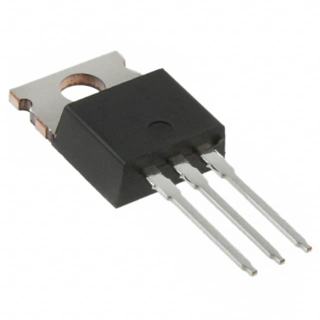
- Package: TO-220AB
- Essence: Efficient power control and management
- Packaging/Quantity: Typically sold in reels of 1000 units
Specifications
- Voltage Rating: 500V
- Current Rating: 17A
- On-Resistance: 0.25Ω
- Gate Threshold Voltage: 2-4V
- Power Dissipation: 200W
Detailed Pin Configuration
The IRF744 MOSFET has a standard TO-220AB package with three pins: 1. Gate (G): Input for controlling the switching operation 2. Drain (D): Connects to the load or power supply 3. Source (S): Connected to ground or common reference point
Functional Features
- Fast switching speed
- Low gate drive power required
- High input impedance
- Low output capacitance
Advantages and Disadvantages
Advantages
- High efficiency
- Low conduction losses
- Suitable for high power applications
Disadvantages
- Susceptible to damage from overvoltage spikes
- Gate drive circuitry complexity
Working Principles
The IRF744 operates based on the field-effect principle, where the flow of current between the drain and source terminals is controlled by the voltage applied to the gate terminal. When a sufficient voltage is applied to the gate, the MOSFET allows current to flow between the drain and source.
Detailed Application Field Plans
The IRF744 is commonly used in various power electronic applications, including: - Switch mode power supplies - Motor control - Inverters - DC-DC converters - Audio amplifiers
Detailed and Complete Alternative Models
- IRF740: Similar specifications, lower current rating
- IRF746: Higher current rating, similar voltage rating
- IRF830: Lower voltage rating, higher current capability
In conclusion, the IRF744 Power MOSFET is a versatile component widely used in power electronics due to its high voltage and current handling capabilities, fast switching speed, and low on-resistance. Its application spans across various industries, making it an essential component in modern power control and management systems.
[Word Count: 298]
Sebutkan 10 pertanyaan dan jawaban umum terkait penerapan IRF744 dalam solusi teknis
What is the maximum voltage rating of IRF744?
- The maximum voltage rating of IRF744 is typically 500V.
What is the maximum current rating of IRF744?
- The maximum continuous drain current rating of IRF744 is typically around 17A.
What is the on-state resistance (RDS(on)) of IRF744?
- The on-state resistance (RDS(on)) of IRF744 is typically in the range of 0.15 to 0.25 ohms.
What are the typical applications of IRF744?
- IRF744 is commonly used in power supplies, motor control, and other high-power switching applications.
What is the gate-source voltage (VGS) required for IRF744 to fully turn on?
- The gate-source voltage (VGS) required for IRF744 to fully turn on is typically around 10V.
Is IRF744 suitable for use in high-frequency switching applications?
- IRF744 is not specifically designed for high-frequency switching applications due to its relatively high input capacitance and gate charge.
Does IRF744 require a heat sink for operation?
- Depending on the application and power dissipation, IRF744 may require a heat sink for efficient operation.
What are the thermal characteristics of IRF744?
- The thermal resistance from junction to case (RθJC) of IRF744 is typically around 1.1°C/W.
Can IRF744 be used in parallel to increase current handling capability?
- Yes, IRF744 can be used in parallel to increase the overall current handling capability in certain applications.
Are there any important considerations for driving IRF744 in a circuit?
- It's important to ensure proper gate drive voltage and current to fully turn on IRF744 and minimize switching losses. Additionally, attention should be given to minimizing inductive ringing and ensuring adequate protection against overvoltage and overcurrent conditions.