

Lihat spesifikasi untuk detail produk.
VF30150C-M3/4W
Product Overview
The VF30150C-M3/4W belongs to the category of power rectifiers and is designed for use in various electronic applications. This diode offers high efficiency, low forward voltage drop, and fast switching capabilities. The package includes a single diode in a compact form factor, making it suitable for space-constrained designs.
Basic Information
- Category: Power Rectifier
- Use: Electronic applications
- Characteristics: High efficiency, low forward voltage drop, fast switching
- Package: Compact single diode
- Essence: Efficient power rectification
- Packaging/Quantity: Single unit packaging
Specifications
- Model: VF30150C-M3/4W
- Type: Power Rectifier Diode
- Voltage Rating: 150V
- Current Rating: 30A
- Package Type: MELF
- Mounting Type: Surface Mount
- Operating Temperature Range: -65°C to +175°C
Detailed Pin Configuration
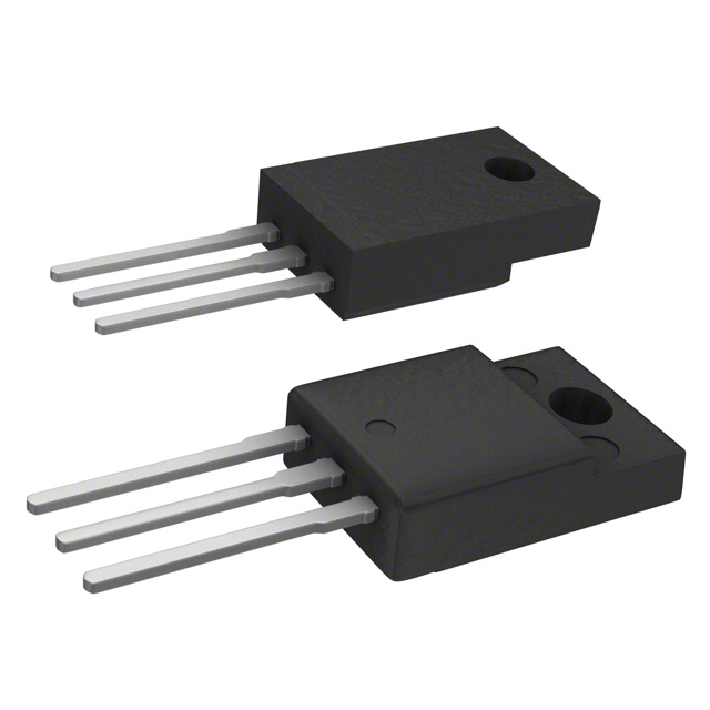
The VF30150C-M3/4W features a standard MELF package with two leads. The pin configuration is as follows: - Pin 1: Anode - Pin 2: Cathode
Functional Features
- High efficiency power rectification
- Low forward voltage drop
- Fast switching characteristics
- Compact and space-saving design
Advantages and Disadvantages
Advantages
- High efficiency
- Low forward voltage drop
- Fast switching
- Compact form factor
Disadvantages
- Limited current rating compared to some higher-power diodes
- Sensitive to overvoltage conditions
Working Principles
The VF30150C-M3/4W operates based on the principles of semiconductor junction behavior. When forward-biased, it allows current flow with minimal voltage drop, enabling efficient power conversion.
Detailed Application Field Plans
The VF30150C-M3/4W is well-suited for various applications, including: - Switch-mode power supplies - LED lighting - Automotive electronics - Industrial power systems
Detailed and Complete Alternative Models
- VF50100C-M3/4W: 100V, 50A power rectifier diode
- VF40100C-M3/4W: 100V, 40A power rectifier diode
- VF30200C-M3/4W: 200V, 30A power rectifier diode
In conclusion, the VF30150C-M3/4W power rectifier diode offers high efficiency and fast switching capabilities, making it suitable for a wide range of electronic applications. Its compact form factor and reliable performance make it a preferred choice for space-constrained designs.
Sebutkan 10 pertanyaan dan jawaban umum terkait penerapan VF30150C-M3/4W dalam solusi teknis
What is the maximum voltage rating of VF30150C-M3/4W?
- The maximum voltage rating of VF30150C-M3/4W is 150V.
What is the maximum forward current of VF30150C-M3/4W?
- The maximum forward current of VF30150C-M3/4W is 30A.
What is the package type of VF30150C-M3/4W?
- VF30150C-M3/4W comes in a TO-220AC package type.
What are the typical applications for VF30150C-M3/4W?
- VF30150C-M3/4W is commonly used in power supplies, inverters, and motor control circuits.
What is the reverse recovery time of VF30150C-M3/4W?
- The reverse recovery time of VF30150C-M3/4W is typically 35ns.
Does VF30150C-M3/4W have overcurrent protection?
- Yes, VF30150C-M3/4W features overcurrent protection to safeguard against excessive currents.
Is VF30150C-M3/4W suitable for high-frequency applications?
- Yes, VF30150C-M3/4W is designed for high-frequency applications due to its fast switching characteristics.
What is the junction temperature range for VF30150C-M3/4W?
- The junction temperature range for VF30150C-M3/4W is -55°C to +175°C.
Does VF30150C-M3/4W require a heatsink for proper operation?
- Depending on the application and operating conditions, a heatsink may be recommended for VF30150C-M3/4W to ensure optimal thermal management.
Can VF30150C-M3/4W be used in parallel for higher current applications?
- Yes, VF30150C-M3/4W can be used in parallel to increase the current handling capability for higher power requirements. However, proper thermal considerations and current sharing mechanisms should be implemented.