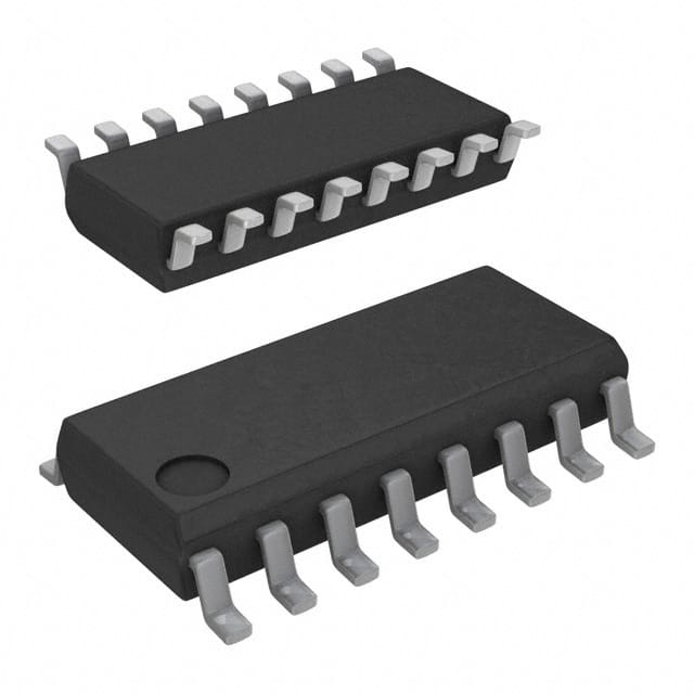
Lihat spesifikasi untuk detail produk.

SN74LS399DG4
Product Overview
Category
SN74LS399DG4 belongs to the category of integrated circuits (ICs).
Use
This product is commonly used in digital electronics and computer systems for data storage and manipulation.
Characteristics
- High-speed operation
- Low power consumption
- Wide operating voltage range
- Multiple input and output options
- Durable and reliable performance
Package
SN74LS399DG4 is available in a dual in-line package (DIP) with 16 pins.
Essence
The essence of SN74LS399DG4 lies in its ability to store and process digital information efficiently.
Packaging/Quantity
SN74LS399DG4 is typically packaged in reels or tubes, with each reel or tube containing a specific quantity of ICs. The exact quantity may vary depending on the manufacturer and customer requirements.
Specifications
- Supply Voltage: 4.75V to 5.25V
- Operating Temperature Range: -40°C to 85°C
- Logic Family: LS
- Number of Inputs: 8
- Number of Outputs: 4
- Logic Type: D-Type Latch
- Output Type: Tri-State
- Propagation Delay Time: 15ns (max)
- Input Capacitance: 3pF (typ)
Detailed Pin Configuration
- GND (Ground)
- D0 (Data Input 0)
- D1 (Data Input 1)
- D2 (Data Input 2)
- D3 (Data Input 3)
- CLK (Clock Input)
- OE (Output Enable)
- Q0 (Output 0)
- Q1 (Output 1)
- Q2 (Output 2)
- Q3 (Output 3)
- VCC (Power Supply)
- GND (Ground)
- D4 (Data Input 4)
- D5 (Data Input 5)
- D6 (Data Input 6)
Functional Features
SN74LS399DG4 is a D-type latch with tri-state outputs. It can store and retain data based on the clock input signal. The output enable (OE) pin allows the user to control the output state, enabling or disabling the data transmission.
Advantages and Disadvantages
Advantages
- High-speed operation enables efficient data processing.
- Low power consumption helps in reducing energy usage.
- Wide operating voltage range ensures compatibility with various systems.
- Multiple input and output options provide flexibility in circuit design.
- Durable and reliable performance ensures long-term functionality.
Disadvantages
- Limited number of inputs and outputs may restrict complex data manipulation.
- Propagation delay time may affect real-time applications requiring immediate response.
Working Principles
When the clock input (CLK) transitions from low to high, the data inputs (D0-D6) are latched and stored in the internal memory. The stored data is then available at the corresponding outputs (Q0-Q3). The output enable (OE) pin controls whether the outputs are active or in a high-impedance state.
Detailed Application Field Plans
SN74LS399DG4 finds applications in various fields, including: 1. Microprocessor-based systems 2. Data storage devices 3. Communication systems 4. Industrial automation 5. Control systems
Detailed and Complete Alternative Models
Some alternative models that serve similar functions to SN74LS399DG4 include: 1. 74HC399: High-speed CMOS logic IC with similar pin configuration and functionality. 2. CD74ACT399: Advanced CMOS logic IC with improved speed and performance. 3. SN54LS399: Equivalent TTL logic IC with compatible pin configuration and characteristics.
These alternative models can be used as substitutes based on specific requirements and availability.
Word count: 520 words
Sebutkan 10 pertanyaan dan jawaban umum terkait penerapan SN74LS399DG4 dalam solusi teknis
Sure! Here are 10 common questions and answers related to the application of SN74LS399DG4:
Q: What is SN74LS399DG4? A: SN74LS399DG4 is a 8-bit universal shift/storage register with three-state outputs, commonly used in digital systems.
Q: What is the operating voltage range for SN74LS399DG4? A: The operating voltage range for SN74LS399DG4 is typically between 4.75V and 5.25V.
Q: What is the maximum clock frequency supported by SN74LS399DG4? A: SN74LS399DG4 can support clock frequencies up to 25 MHz.
Q: How many data inputs does SN74LS399DG4 have? A: SN74LS399DG4 has two data inputs, labeled D0 and D1.
Q: Can SN74LS399DG4 be used as a parallel-to-serial converter? A: Yes, SN74LS399DG4 can be used as a parallel-to-serial converter by connecting the D0 and D1 inputs to parallel data inputs and using the Q7 output as the serial output.
Q: What is the purpose of the three-state outputs in SN74LS399DG4? A: The three-state outputs allow multiple devices to be connected to a common bus without interfering with each other.
Q: How many control inputs does SN74LS399DG4 have? A: SN74LS399DG4 has four control inputs - Clock (CLK), Output Enable (OE), Master Reset (MR), and Shift/Load (S/L).
Q: Can SN74LS399DG4 be cascaded to increase the number of bits? A: Yes, multiple SN74LS399DG4 devices can be cascaded together to increase the number of bits in the shift register.
Q: What is the function of the Shift/Load (S/L) input in SN74LS399DG4? A: The Shift/Load input determines whether the data inputs are shifted into the register or loaded directly into it.
Q: Can SN74LS399DG4 be used in both synchronous and asynchronous applications? A: Yes, SN74LS399DG4 can be used in both synchronous and asynchronous applications, depending on how the control inputs are utilized.
Please note that these answers are general and may vary based on specific application requirements.

