Lihat spesifikasi untuk detail produk.

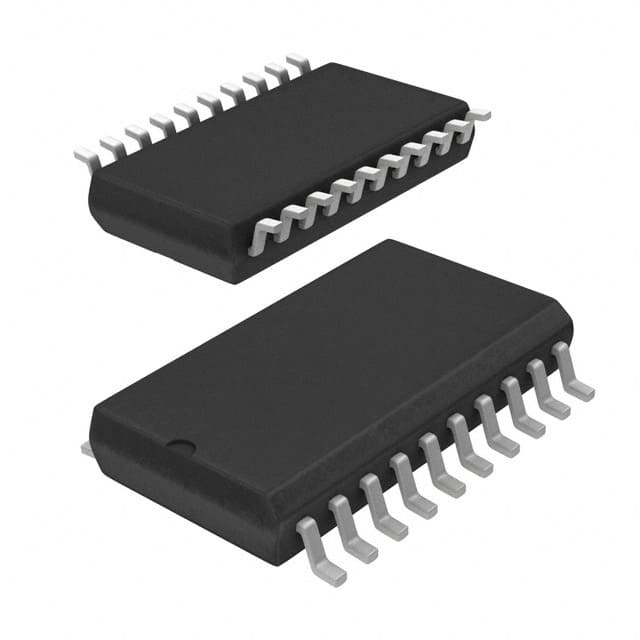
CY74FCT244ATSOC
Product Overview
Category
CY74FCT244ATSOC belongs to the category of integrated circuits (ICs).
Use
This IC is commonly used for signal amplification and buffering in digital systems.
Characteristics
- High-speed operation
- Low power consumption
- Wide operating voltage range
- Compatibility with various logic families
Package
CY74FCT244ATSOC is available in a small outline integrated circuit (SOIC) package.
Essence
The essence of CY74FCT244ATSOC lies in its ability to provide reliable signal amplification and buffering, ensuring smooth data transmission within digital systems.
Packaging/Quantity
CY74FCT244ATSOC is typically packaged in reels or tubes, with quantities varying based on customer requirements.
Specifications
- Supply Voltage: 4.5V to 5.5V
- Input Voltage Range: 0V to VCC
- Output Voltage Range: 0V to VCC
- Operating Temperature Range: -40°C to +85°C
- Logic Family: FCT
- Number of Channels: 8
- Input/Output Type: Non-Inverting
- Propagation Delay: 3.5ns (typical)
Detailed Pin Configuration
CY74FCT244ATSOC consists of 20 pins, each serving a specific function. The pin configuration is as follows:
- A1 - Input A1
- Y1 - Output Y1
- A2 - Input A2
- Y2 - Output Y2
- GND - Ground
- Y3 - Output Y3
- A3 - Input A3
- Y4 - Output Y4
- A4 - Input A4
- Y5 - Output Y5
- A5 - Input A5
- Y6 - Output Y6
- A6 - Input A6
- Y7 - Output Y7
- A7 - Input A7
- Y8 - Output Y8
- OE - Output Enable
- VCC - Supply Voltage
- GND - Ground
- A8 - Input A8
Functional Features
- Non-inverting buffer with 3-state outputs
- High-speed operation allows for efficient data transmission
- Wide operating voltage range enables compatibility with various systems
- 3-state outputs provide flexibility in controlling signal flow
Advantages and Disadvantages
Advantages
- High-speed operation ensures quick data transfer
- Low power consumption minimizes energy usage
- Wide operating voltage range enhances compatibility
- 3-state outputs offer flexibility in signal control
Disadvantages
- Limited number of channels (8)
- Propagation delay may impact real-time applications
Working Principles
CY74FCT244ATSOC operates as a non-inverting buffer, amplifying and buffering digital signals. The inputs are connected to the A1-A8 pins, while the amplified outputs are available at the Y1-Y8 pins. The OE pin controls the output enable/disable functionality.
Detailed Application Field Plans
CY74FCT244ATSOC finds application in various digital systems, including: - Microprocessors - Memory interfaces - Data communication systems - Industrial automation
Its ability to amplify and buffer signals makes it suitable for any application requiring reliable signal transmission.
Detailed and Complete Alternative Models
Some alternative models that serve similar functions to CY74FCT244ATSOC include: - SN74FCT244A - MC74FCT244A - CD74FCT244
These alternatives can be considered based on specific requirements and availability.
Word count: 446 words
Sebutkan 10 pertanyaan dan jawaban umum terkait penerapan CY74FCT244ATSOC dalam solusi teknis
Sure! Here are 10 common questions and answers related to the application of CY74FCT244ATSOC:
Q: What is CY74FCT244ATSOC? A: CY74FCT244ATSOC is a specific type of integrated circuit (IC) known as a buffer/line driver. It is commonly used in digital systems for signal buffering and level shifting.
Q: What is the purpose of using CY74FCT244ATSOC in technical solutions? A: The main purpose of using CY74FCT244ATSOC is to ensure proper signal integrity by buffering and amplifying digital signals, especially when there is a need for driving long or capacitive loads.
Q: What voltage levels does CY74FCT244ATSOC support? A: CY74FCT244ATSOC supports both TTL (Transistor-Transistor Logic) and CMOS (Complementary Metal-Oxide-Semiconductor) voltage levels, making it compatible with a wide range of digital systems.
Q: Can CY74FCT244ATSOC be used bidirectionally? A: Yes, CY74FCT244ATSOC can be used bidirectionally. It has separate input and output pins, allowing data to flow in both directions.
Q: What is the maximum operating frequency of CY74FCT244ATSOC? A: The maximum operating frequency of CY74FCT244ATSOC is typically around 100 MHz, but it can vary depending on the specific conditions and system requirements.
Q: How many channels does CY74FCT244ATSOC have? A: CY74FCT244ATSOC has 8 channels, meaning it can handle up to 8 individual signals simultaneously.
Q: Is CY74FCT244ATSOC tolerant to voltage spikes or noise? A: Yes, CY74FCT244ATSOC has built-in protection against voltage spikes and noise. It includes features like input hysteresis and ESD (Electrostatic Discharge) protection.
Q: Can CY74FCT244ATSOC be cascaded with other ICs? A: Yes, CY74FCT244ATSOC can be easily cascaded with other ICs to expand the number of channels or to create more complex digital systems.
Q: What is the power supply voltage range for CY74FCT244ATSOC? A: The power supply voltage range for CY74FCT244ATSOC is typically between 4.5V and 5.5V, which is commonly used in many digital systems.
Q: Are there any specific precautions to consider when using CY74FCT244ATSOC? A: It is important to ensure proper decoupling and bypass capacitors are used near the power supply pins of CY74FCT244ATSOC to minimize noise and voltage fluctuations. Additionally, following the recommended operating conditions and layout guidelines provided in the datasheet is crucial for optimal performance.
Please note that these answers are general and may vary depending on the specific datasheet and manufacturer's recommendations for CY74FCT244ATSOC.

