

Lihat spesifikasi untuk detail produk.
CDCVF2510APWR
Product Overview
Category: Integrated Circuit (IC)
Use: Clock Driver
Characteristics: - Low voltage, low skew clock driver - High-speed operation - Wide operating voltage range - Small package size - Low power consumption
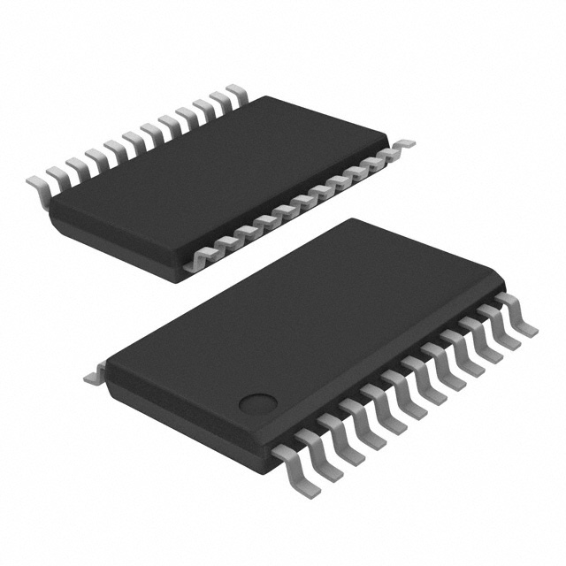
Package: TSSOP (Thin Shrink Small Outline Package)
Essence: The CDCVF2510APWR is a clock driver IC designed to distribute high-frequency clock signals with low skew and low voltage levels.
Packaging/Quantity: The CDCVF2510APWR is available in a TSSOP package. It is typically sold in reels of 2500 units.
Specifications
- Supply Voltage Range: 2.3V to 3.6V
- Input Frequency Range: 0Hz to 200MHz
- Output Skew: 100ps (maximum)
- Output Voltage Swing: 0V to VDD
- Operating Temperature Range: -40°C to +85°C
Detailed Pin Configuration
The CDCVF2510APWR has a total of 20 pins. The pin configuration is as follows:
- OE (Output Enable)
- Q0 (Output 0)
- GND (Ground)
- Q1 (Output 1)
- Q2 (Output 2)
- Q3 (Output 3)
- Q4 (Output 4)
- Q5 (Output 5)
- VDD (Power Supply)
- Q6 (Output 6)
- Q7 (Output 7)
- Q8 (Output 8)
- Q9 (Output 9)
- Q10 (Output 10)
- Q11 (Output 11)
- Q12 (Output 12)
- Q13 (Output 13)
- Q14 (Output 14)
- Q15 (Output 15)
- GND (Ground)
Functional Features
- Low skew clock distribution: The CDCVF2510APWR ensures that clock signals are distributed with minimal time delay between outputs, reducing skew.
- Wide operating voltage range: It can operate within a wide voltage range of 2.3V to 3.6V, making it compatible with various systems.
- High-speed operation: The IC supports clock frequencies up to 200MHz, enabling it to handle high-speed data transmission.
- Output enable control: The OE pin allows the user to enable or disable the outputs as needed.
Advantages and Disadvantages
Advantages: - Low skew clock distribution ensures accurate synchronization in complex systems. - Wide operating voltage range provides flexibility in different applications. - Small package size saves board space. - Low power consumption helps reduce overall system power requirements.
Disadvantages: - Limited number of output channels (15 in total). - Not suitable for applications requiring a higher number of output channels.
Working Principles
The CDCVF2510APWR operates by receiving an input clock signal and distributing it to multiple output channels. It uses internal circuitry to buffer and amplify the input signal, ensuring that each output receives a clean and synchronized clock signal. The low skew feature minimizes timing differences between outputs, maintaining accurate synchronization in the system.
Detailed Application Field Plans
The CDCVF2510APWR is commonly used in various electronic systems where precise clock distribution is crucial. Some application fields include:
- Communication Systems: Used in routers, switches, and network equipment to synchronize data transmission.
- Computer Systems: Employed in servers, workstations, and motherboards to distribute clock signals to various components.
- Test and Measurement Equipment: Utilized in oscilloscopes, logic analyzers, and signal generators to synchronize measurement and analysis processes.
- Industrial Automation: Integrated into control systems, PLCs, and robotics to ensure accurate timing in industrial processes.
Detailed and Complete Alternative Models
- CDCVF2510APW: Similar to CDCVF2510APWR but available in a different package (TSSOP-20).
- CDCVF2510APWRE4: RoHS-compliant version of CDCVF2510APWR with the same specifications and features.
- CDCVF2510APWT: Tape and reel packaging option for CDCVF2510APWR.
These alternative models offer similar functionality and can be considered as substitutes for the CDCVF2510APWR depending on specific requirements.
Word count: 511 words
Sebutkan 10 pertanyaan dan jawaban umum terkait penerapan CDCVF2510APWR dalam solusi teknis
Sure! Here are 10 common questions and answers related to the application of CDCVF2510APWR in technical solutions:
Q: What is CDCVF2510APWR? A: CDCVF2510APWR is a high-performance clock driver IC manufactured by Texas Instruments.
Q: What is the purpose of CDCVF2510APWR? A: CDCVF2510APWR is designed to distribute and buffer clock signals in various electronic systems.
Q: What is the operating voltage range of CDCVF2510APWR? A: CDCVF2510APWR operates within a voltage range of 2.375V to 3.6V.
Q: How many outputs does CDCVF2510APWR have? A: CDCVF2510APWR has 10 outputs, which can be individually enabled or disabled.
Q: What is the maximum output frequency supported by CDCVF2510APWR? A: CDCVF2510APWR supports a maximum output frequency of 250 MHz.
Q: Can CDCVF2510APWR generate different output frequencies simultaneously? A: No, CDCVF2510APWR generates the same output frequency on all its outputs.
Q: Does CDCVF2510APWR support differential clock inputs? A: Yes, CDCVF2510APWR supports both single-ended and differential clock inputs.
Q: What is the typical propagation delay of CDCVF2510APWR? A: The typical propagation delay of CDCVF2510APWR is around 1.5 ns.
Q: Is CDCVF2510APWR compatible with other clock driver ICs? A: Yes, CDCVF2510APWR is compatible with other clock driver ICs and can be used in conjunction with them.
Q: What are some common applications of CDCVF2510APWR? A: CDCVF2510APWR is commonly used in networking equipment, telecommunications systems, data centers, and high-speed digital designs.
Please note that these answers are general and may vary depending on the specific requirements and use cases. It's always recommended to refer to the datasheet and consult with technical experts for accurate information.