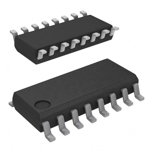
Lihat spesifikasi untuk detail produk.

CD74HCT4046AM96G4
Overview
Category
CD74HCT4046AM96G4 belongs to the category of integrated circuits (ICs).
Use
This IC is commonly used in electronic devices for frequency synthesis and phase-locked loop (PLL) applications.
Characteristics
- High-speed operation
- Low power consumption
- Wide operating voltage range
- Excellent noise immunity
- Compact package size
Package
CD74HCT4046AM96G4 is available in a small outline integrated circuit (SOIC) package.
Essence
The essence of CD74HCT4046AM96G4 lies in its ability to generate stable and accurate frequencies, making it suitable for various applications requiring precise timing control.
Packaging/Quantity
This IC is typically packaged in reels or tubes, with a quantity of 2500 units per reel/tube.
Specifications and Parameters
- Supply Voltage: 2V to 6V
- Operating Temperature Range: -40°C to +85°C
- Input Voltage Range: 0V to VCC
- Output Voltage Range: 0V to VCC
- Maximum Clock Frequency: 25MHz
Pin Configuration
The CD74HCT4046AM96G4 IC has a total of 16 pins. The detailed pin configuration is as follows:
- Pin 1: Phase Comparator 1 Input
- Pin 2: Phase Comparator 1 Output
- Pin 3: Phase Comparator 1 Ground
- Pin 4: Phase Comparator 2 Input
- Pin 5: Phase Comparator 2 Output
- Pin 6: Phase Comparator 2 Ground
- Pin 7: Voltage-Controlled Oscillator (VCO) Control Voltage Input
- Pin 8: VCO Ground
- Pin 9: VCO Output
- Pin 10: VCO Power Supply
- Pin 11: Lock Detect Output
- Pin 12: Lock Detect Ground
- Pin 13: Reference Frequency Input
- Pin 14: Reference Frequency Ground
- Pin 15: Phase Comparator 1 and 2 Power Supply
- Pin 16: Phase Comparator 1 and 2 Ground
Functional Characteristics
CD74HCT4046AM96G4 offers the following functional characteristics:
- Two phase comparators for precise frequency comparison
- Voltage-controlled oscillator (VCO) for generating stable output frequencies
- Lock detect output for indicating locked state
- Wide operating voltage range for flexibility in various applications
Advantages and Disadvantages
Advantages
- High-speed operation allows for quick frequency synthesis
- Low power consumption for energy-efficient designs
- Excellent noise immunity ensures reliable performance
- Compact package size enables space-saving integration
Disadvantages
- Limited maximum clock frequency of 25MHz may not be suitable for high-frequency applications
- Requires external components for complete PLL implementation
Applicable Range of Products
CD74HCT4046AM96G4 is widely applicable in the following products and industries:
- Communication systems
- Audio equipment
- Test and measurement instruments
- Industrial automation
- Consumer electronics
Working Principles
The CD74HCT4046AM96G4 operates based on the principles of phase-locked loop (PLL). It compares the phase and frequency of an input signal with a reference signal, adjusts the voltage-controlled oscillator accordingly, and generates an output signal with the desired frequency and phase relationship.
Detailed Application Field Plans
CD74HCT4046AM96G4 can be utilized in various application fields, including:
- Frequency synthesizers for wireless communication systems
- Clock generation in digital audio equipment
- Frequency modulation (FM) demodulation circuits
- Phase-locked loop (PLL) circuits for frequency stabilization
- Frequency tracking and synchronization systems
Detailed Alternative Models
Some alternative models to CD74HCT4046AM96G4 include:
- CD4046BE
- MC14046BCL
- HEF4046BT
- SN74LS46N
- MM74C4046N
5 Common Technical Questions and Answers
Q: What is the maximum operating voltage of CD74HCT4046AM96G4? A: The IC can operate within a voltage range of 2V to 6V.
Q: Can CD74HCT4046AM96G4 be used in high-frequency applications? A: No, the maximum clock frequency supported by this IC is 25MHz, which may not be suitable for high-frequency applications.
Q: What is the purpose of the lock detect output pin? A: The lock detect output pin indicates whether the PLL is locked onto

