

Lihat spesifikasi untuk detail produk.
MC74HC138ADTR2G
Product Overview
- Category: Integrated Circuit (IC)
- Use: Decoder/Demultiplexer
- Characteristics: High-Speed CMOS Logic, 3-to-8 Line Decoder/Demultiplexer
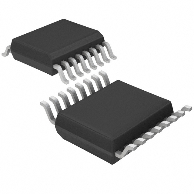
- Package: TSSOP-16
- Essence: Decodes a three-bit binary input to one of eight outputs
- Packaging/Quantity: Tape and Reel, 2500 units per reel
Specifications
- Supply Voltage Range: 2V to 6V
- High-Level Input Voltage: 2V
- Low-Level Input Voltage: 0.8V
- High-Level Output Current: -4mA
- Low-Level Output Current: 4mA
- Propagation Delay Time: 15ns
- Operating Temperature Range: -40°C to +85°C
Detailed Pin Configuration
- GND (Ground)
- A0 (Address Input Bit 0)
- A1 (Address Input Bit 1)
- A2 (Address Input Bit 2)
- E1 (Enable Input 1)
- E2 (Enable Input 2)
- Y0 (Output 0)
- Y1 (Output 1)
- Y2 (Output 2)
- Y3 (Output 3)
- Y4 (Output 4)
- Y5 (Output 5)
- Y6 (Output 6)
- Y7 (Output 7)
- VCC (Positive Power Supply)
Functional Features
The MC74HC138ADTR2G is a high-speed CMOS logic decoder/demultiplexer IC. It decodes a three-bit binary input to one of eight outputs. The enable inputs (E1 and E2) control the operation of the device. When both enable inputs are high, the outputs are in a high-impedance state. The outputs become active when one of the enable inputs is low.
Advantages and Disadvantages
Advantages: - High-speed operation - Wide supply voltage range - Low power consumption - Compact TSSOP-16 package
Disadvantages: - Limited number of input bits (3-bit) - Limited number of output lines (8 lines)
Working Principles
The MC74HC138ADTR2G works based on the principle of binary decoding. It takes a three-bit binary input and activates one of the eight output lines based on the input combination. The enable inputs control the activation of the outputs. When both enable inputs are high, the outputs are disabled.
Detailed Application Field Plans
The MC74HC138ADTR2G can be used in various applications, including but not limited to: - Address decoding in microcontrollers and microprocessors - Memory selection in digital systems - Data routing in communication systems - Signal demultiplexing in multiplexers
Alternative Models
Some alternative models that provide similar functionality to MC74HC138ADTR2G include: - 74LS138 - CD74HC138E - SN74LS138N - 74HCT138
These models have different package options and may vary in terms of speed, power consumption, and voltage range. Users should select the model that best suits their specific requirements.
Word count: 305 words
Sebutkan 10 pertanyaan dan jawaban umum terkait penerapan MC74HC138ADTR2G dalam solusi teknis
Sure! Here are 10 common questions and answers related to the application of MC74HC138ADTR2G in technical solutions:
Q: What is MC74HC138ADTR2G? A: MC74HC138ADTR2G is a 3-to-8 line decoder/demultiplexer integrated circuit (IC) commonly used in digital electronics.
Q: What is the purpose of MC74HC138ADTR2G? A: The purpose of MC74HC138ADTR2G is to decode binary information from a microcontroller or other digital device into multiple output lines.
Q: How many input lines does MC74HC138ADTR2G have? A: MC74HC138ADTR2G has three input lines, which can represent up to eight different combinations.
Q: How many output lines does MC74HC138ADTR2G have? A: MC74HC138ADTR2G has eight output lines, each corresponding to a specific combination of the input lines.
Q: What is the voltage range supported by MC74HC138ADTR2G? A: MC74HC138ADTR2G supports a voltage range of 2V to 6V, making it compatible with various digital systems.
Q: Can MC74HC138ADTR2G be used for both decoding and demultiplexing? A: Yes, MC74HC138ADTR2G can be used as both a decoder and a demultiplexer, depending on the application requirements.
Q: What is the maximum current that MC74HC138ADTR2G can source or sink per output pin? A: MC74HC138ADTR2G can source or sink up to 25mA per output pin, making it suitable for driving LEDs or other low-power devices.
Q: Can MC74HC138ADTR2G be cascaded to increase the number of output lines? A: Yes, multiple MC74HC138ADTR2G ICs can be cascaded together to increase the number of output lines and decode more complex combinations.
Q: Is MC74HC138ADTR2G compatible with both TTL and CMOS logic levels? A: Yes, MC74HC138ADTR2G is compatible with both TTL and CMOS logic levels, allowing it to interface with a wide range of digital devices.
Q: What are some common applications of MC74HC138ADTR2G? A: MC74HC138ADTR2G is commonly used in address decoding, memory selection, data routing, and general-purpose digital logic circuits.
Please note that these answers are general and may vary depending on specific application requirements and datasheet specifications.