

Lihat spesifikasi untuk detail produk.
MC10E445FNR2
Product Overview
Category: Integrated Circuit (IC)
Use: The MC10E445FNR2 is a high-speed, low-power quad differential line receiver designed for use in digital communication systems. It is commonly used in applications that require reliable data transmission over long distances.
Characteristics: - High-speed operation - Low power consumption - Differential input and output - Wide operating voltage range - Robust design for noise immunity
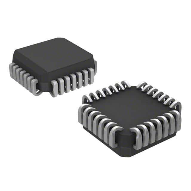
Package: The MC10E445FNR2 is available in a small outline integrated circuit (SOIC) package. This package provides protection and easy handling during installation.
Essence: The essence of the MC10E445FNR2 lies in its ability to receive differential signals and convert them into logic-level outputs. It ensures accurate and reliable data reception in digital communication systems.
Packaging/Quantity: The MC10E445FNR2 is typically sold in reels containing 250 units per reel.
Specifications
- Supply Voltage Range: +3.0V to +5.5V
- Input Common Mode Voltage Range: -2.0V to +7.0V
- Operating Temperature Range: -40°C to +85°C
- Maximum Input Clock Frequency: 1.6 GHz
- Propagation Delay: 1.8 ns
Detailed Pin Configuration
The MC10E445FNR2 has a total of 20 pins. The pin configuration is as follows:
- VCC
- Q0
- Q1
- Q2
- Q3
- /Q0
- /Q1
- /Q2
- /Q3
- GND
- D0
- D1
- D2
- D3
- /D0
- /D1
- /D2
- /D3
- CLK
- /CLK
Functional Features
- Differential Line Reception: The MC10E445FNR2 is designed to receive differential signals, allowing for noise rejection and improved signal integrity.
- High-Speed Operation: With a maximum input clock frequency of 1.6 GHz, the IC enables high-speed data transmission.
- Low Power Consumption: The IC operates at low power, making it suitable for battery-powered devices.
- Wide Operating Voltage Range: The supply voltage range of +3.0V to +5.5V allows for compatibility with various systems.
Advantages and Disadvantages
Advantages: - Reliable data reception over long distances - High-speed operation for fast data transmission - Low power consumption for energy efficiency - Robust design for noise immunity
Disadvantages: - Limited availability in certain regions - Requires careful handling during installation due to small package size
Working Principles
The MC10E445FNR2 works by receiving differential signals on its input pins and converting them into logic-level outputs. It utilizes internal circuitry to amplify and process the received signals, ensuring accurate data reception. The IC's robust design helps minimize the impact of noise and interference, resulting in reliable communication.
Detailed Application Field Plans
The MC10E445FNR2 finds applications in various digital communication systems, including: - Telecommunications - Networking equipment - Data centers - Industrial automation - Test and measurement instruments
In these fields, the IC is used to receive and process differential signals, enabling reliable data transmission over long distances.
Detailed and Complete Alternative Models
- MC100EP445FAG: Similar functionality with enhanced performance characteristics.
- MC100ELT21DR2G: Differential line receiver with lower power consumption.
- MC100LVELT22DR2G: High-speed differential line receiver with extended temperature range.
These alternative models offer similar functionality to the MC10E445FNR2, catering to different performance requirements and specifications.
Word count: 511 words
Sebutkan 10 pertanyaan dan jawaban umum terkait penerapan MC10E445FNR2 dalam solusi teknis
Sure! Here are 10 common questions and answers related to the application of MC10E445FNR2 in technical solutions:
Q: What is MC10E445FNR2? A: MC10E445FNR2 is a specific integrated circuit (IC) that belongs to the MC10E series of high-speed logic devices.
Q: What is the purpose of MC10E445FNR2? A: MC10E445FNR2 is primarily used for clock distribution, synchronization, and signal conditioning in high-speed digital systems.
Q: What is the operating voltage range of MC10E445FNR2? A: The operating voltage range of MC10E445FNR2 is typically between -4.2V and -5.7V.
Q: What is the maximum frequency at which MC10E445FNR2 can operate? A: MC10E445FNR2 can operate at frequencies up to 1.6 GHz, making it suitable for high-speed applications.
Q: Can MC10E445FNR2 be used in both single-ended and differential signaling applications? A: Yes, MC10E445FNR2 supports both single-ended and differential signaling, providing flexibility in various system designs.
Q: Does MC10E445FNR2 have built-in input termination resistors? A: No, MC10E445FNR2 does not have built-in input termination resistors. External termination components may be required.
Q: What is the output swing capability of MC10E445FNR2? A: MC10E445FNR2 has a typical output swing of ±1.3V, allowing for compatibility with different logic families.
Q: Can MC10E445FNR2 be used in low-power applications? A: No, MC10E445FNR2 is not specifically designed for low-power applications. It is more suitable for high-speed and high-performance systems.
Q: Are there any specific layout considerations for using MC10E445FNR2? A: Yes, proper PCB layout techniques should be followed to minimize noise, ensure signal integrity, and optimize performance.
Q: Where can I find more information about the application of MC10E445FNR2? A: You can refer to the datasheet and application notes provided by the manufacturer or consult technical resources and forums for further guidance.
Please note that the answers provided here are general and may vary depending on specific design requirements and application scenarios.