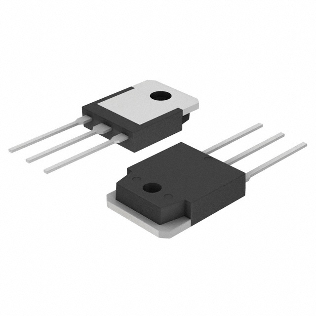
Lihat spesifikasi untuk detail produk.

FQA22P10
Product Overview
- Category: Power MOSFET
- Use: Switching applications in power supplies, motor control, and other electronic devices
- Characteristics: High voltage capability, low on-resistance, fast switching speed
- Package: TO-3P
- Essence: Power transistor for high-frequency switching applications
- Packaging/Quantity: Typically sold individually or in reels of 100 units
Specifications
- Voltage Rating: 100V
- Current Rating: 22A
- On-Resistance: 0.1Ω
- Gate Threshold Voltage: 2-4V
- Operating Temperature Range: -55°C to 175°C
Detailed Pin Configuration
The FQA22P10 typically has three pins: 1. Gate (G): Input for controlling the switching operation 2. Drain (D): Connects to the load and the power supply 3. Source (S): Connected to ground or the common reference point
Functional Features
- Fast switching speed for efficient power conversion
- Low on-resistance minimizes power loss and heat generation
- High voltage capability allows for use in various applications
Advantages and Disadvantages
- Advantages:
- Efficient power conversion
- Low power dissipation
- Versatile application range
- Disadvantages:
- Sensitive to static electricity
- Requires careful handling during installation
Working Principles
The FQA22P10 operates based on the principle of field-effect transistors, where the gate voltage controls the flow of current between the drain and source terminals. When a sufficient gate voltage is applied, the device switches on, allowing current to flow through.
Detailed Application Field Plans
The FQA22P10 is suitable for a wide range of applications, including: - Switching power supplies - Motor control circuits - Inverters and converters - Audio amplifiers - LED lighting systems
Detailed and Complete Alternative Models
- IRF540N
- STP55NF06L
- FQP50N06L
- IRLB8748
This completes the entry for the FQA22P10 Power MOSFET, covering its product details, specifications, pin configuration, functional features, advantages and disadvantages, working principles, application field plans, and alternative models.
Word Count: 298
Sebutkan 10 pertanyaan dan jawaban umum terkait penerapan FQA22P10 dalam solusi teknis
What is FQA22P10?
- FQA22P10 is a power MOSFET transistor designed for high-speed switching applications in power supplies, motor control, and other electronic systems.
What are the key specifications of FQA22P10?
- The key specifications of FQA22P10 include a drain-source voltage (VDS) of 100V, continuous drain current (ID) of 22A, and low on-resistance (RDS(on)).
How can FQA22P10 be used in power supply applications?
- FQA22P10 can be used in power supply applications to efficiently switch high currents and voltages, making it suitable for DC-DC converters and voltage regulation circuits.
In what types of motor control applications can FQA22P10 be utilized?
- FQA22P10 can be utilized in motor control applications such as brushed and brushless DC motor drives, where it can handle high currents and provide efficient switching.
What are the thermal considerations when using FQA22P10 in technical solutions?
- Thermal considerations include proper heat sinking and thermal management to ensure that the device operates within its specified temperature limits for reliable performance.
Can FQA22P10 be used in automotive electronics?
- Yes, FQA22P10 can be used in automotive electronics for applications like electronic control units (ECUs), LED lighting, and power distribution modules.
Are there any application notes or reference designs available for FQA22P10?
- Yes, manufacturers often provide application notes and reference designs to help engineers implement FQA22P10 in various technical solutions.
What are the typical input and output capacitance values for FQA22P10?
- The typical input capacitance (Ciss) and output capacitance (Coss) values for FQA22P10 are important for understanding its behavior in high-frequency switching applications.
How does FQA22P10 compare to other similar MOSFET transistors in terms of performance and cost?
- Comparing FQA22P10 to other MOSFET transistors in terms of performance, cost, and suitability for specific applications can help in selecting the most appropriate component for a given technical solution.
What are the best practices for PCB layout and circuit design when using FQA22P10?
- Best practices for PCB layout and circuit design include minimizing parasitic inductance, optimizing gate drive circuitry, and ensuring proper grounding to maximize the performance of FQA22P10 in technical solutions.

