

Lihat spesifikasi untuk detail produk.
74LVQ157SJ
Basic Information Overview
- Category: Integrated Circuit (IC)
- Use: Multiplexer/Demultiplexer
- Characteristics: Low-voltage, Quad 2-input multiplexer/demultiplexer
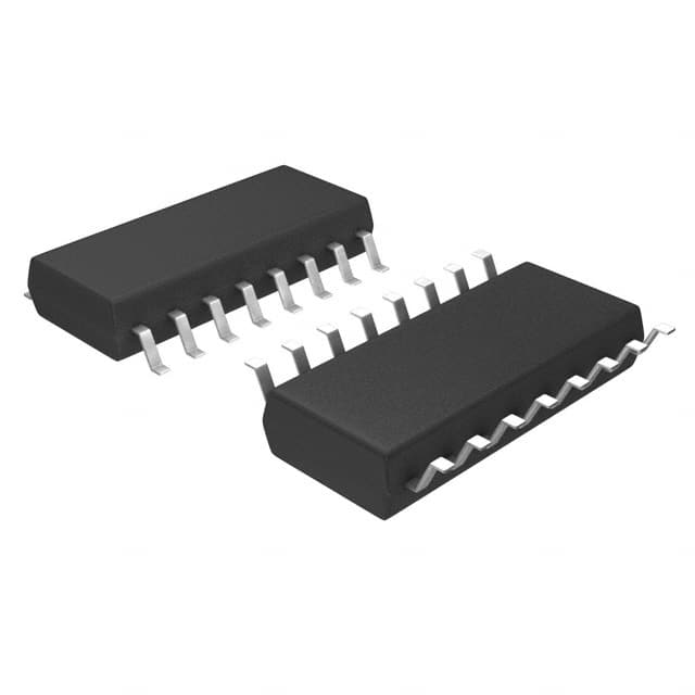
- Package: SOIC (Small Outline Integrated Circuit)
- Essence: Logic gate IC used for data routing and selection
- Packaging/Quantity: Available in reels or tubes, typically sold in quantities of 250 or 1000 units
Specifications
- Supply Voltage Range: 1.65V to 5.5V
- Input Voltage Range: -0.5V to VCC + 0.5V
- Output Voltage Range: 0V to VCC
- Operating Temperature Range: -40°C to +85°C
- Logic Family: LVQ (Low-Voltage CMOS Quad)
Detailed Pin Configuration
The 74LVQ157SJ IC has a total of 16 pins, which are assigned specific functions as follows:
| Pin Number | Pin Name | Function | |------------|----------|----------| | 1 | A | Data Input A | | 2 | B | Data Input B | | 3 | C | Data Input C | | 4 | D | Data Input D | | 5 | GND | Ground (0V) | | 6 | Y | Multiplexer/Demultiplexer Output | | 7 | E | Enable Input | | 8 | F | Select Input | | 9-16 | NC | No Connection |
Functional Features
- Quad 2-input multiplexer/demultiplexer with common select and enable inputs
- Can be used as a 2-to-1 multiplexer or a 1-to-2 demultiplexer
- Low-voltage operation allows compatibility with a wide range of systems
- High-speed operation for efficient data routing and selection
- Low power consumption for energy-efficient applications
Advantages and Disadvantages
Advantages: - Versatile functionality as both a multiplexer and demultiplexer - Wide supply voltage range allows compatibility with various systems - Compact SOIC package for space-saving designs - High-speed operation enables efficient data processing
Disadvantages: - Limited number of inputs and outputs compared to larger multiplexers/demultiplexers - Not suitable for high-voltage applications
Working Principles
The 74LVQ157SJ operates based on the principles of digital logic. It uses the select (F) and enable (E) inputs to control the routing of data from the four input pins (A, B, C, D) to the output pin (Y). The select input determines whether the IC functions as a multiplexer or a demultiplexer. When the enable input is active, the selected input is routed to the output pin. Otherwise, the output remains in a high-impedance state.
Detailed Application Field Plans
The 74LVQ157SJ finds applications in various fields, including: 1. Data communication systems 2. Digital signal processing 3. Multiplexing audio/video signals 4. Industrial automation 5. Consumer electronics
Detailed and Complete Alternative Models
Some alternative models that offer similar functionality to the 74LVQ157SJ are: 1. 74HC157: High-speed CMOS Quad 2-input multiplexer/demultiplexer 2. CD4051: Analog multiplexer/demultiplexer IC 3. SN74LS151: TTL Quad 2-input multiplexer
These alternative models can be considered based on specific requirements and system compatibility.
Word count: 349 words
Sebutkan 10 pertanyaan dan jawaban umum terkait penerapan 74LVQ157SJ dalam solusi teknis
Sure! Here are 10 common questions and answers related to the application of 74LVQ157SJ in technical solutions:
Question: What is the 74LVQ157SJ?
Answer: The 74LVQ157SJ is a quad 2-input multiplexer with 3-state outputs, commonly used in digital logic circuits.Question: What is the operating voltage range for the 74LVQ157SJ?
Answer: The operating voltage range for the 74LVQ157SJ is typically between 2.7V and 5.5V.Question: What is the maximum frequency at which the 74LVQ157SJ can operate?
Answer: The 74LVQ157SJ can typically operate at frequencies up to 100MHz.Question: Can the 74LVQ157SJ handle both analog and digital signals?
Answer: No, the 74LVQ157SJ is designed specifically for digital signals and is not suitable for handling analog signals.Question: How many inputs does the 74LVQ157SJ have?
Answer: The 74LVQ157SJ has four inputs, labeled A, B, C, and D.Question: How many output channels does the 74LVQ157SJ have?
Answer: The 74LVQ157SJ has four output channels, labeled Y0, Y1, Y2, and Y3.Question: Can the outputs of the 74LVQ157SJ be put into a high-impedance state?
Answer: Yes, the outputs of the 74LVQ157SJ can be put into a high-impedance state by enabling the 3-state outputs.Question: What is the purpose of the enable pin (G)?
Answer: The enable pin (G) is used to control the 3-state outputs of the 74LVQ157SJ. When G is low, the outputs are enabled; when G is high, the outputs are in a high-impedance state.Question: Can the 74LVQ157SJ be cascaded to increase the number of inputs or outputs?
Answer: Yes, multiple 74LVQ157SJ chips can be cascaded together to increase the number of inputs or outputs in a digital circuit.Question: What are some common applications for the 74LVQ157SJ?
Answer: The 74LVQ157SJ is commonly used in multiplexing and data selection applications, such as in data buses, address decoding, and signal routing in microcontrollers, CPUs, and other digital systems.
Please note that these answers are general and may vary depending on specific application requirements and datasheet specifications.