

Lihat spesifikasi untuk detail produk.
PDTC114YE,135
Product Category:
The PDTC114YE,135 belongs to the category of semiconductor devices, specifically within the realm of transistors.
Basic Information Overview:
- Use: The PDTC114YE,135 is primarily used as a switching transistor in various electronic circuits.
- Characteristics: This product is known for its high-speed switching capability and low power consumption.
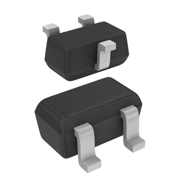
- Package: It is available in a SOT416 (SC-75) package.
- Essence: The essence of this product lies in its ability to efficiently control the flow of current in electronic circuits.
- Packaging/Quantity: The PDTC114YE,135 is typically packaged in reels with a quantity varying based on customer requirements.
Specifications:
- Voltage - Collector Emitter Breakdown (Max): 50V
- Current - Collector (Ic) (Max): 100mA
- Power - Max: 150mW
- DC Current Gain (hFE) (Min) @ Ic, Vce: 100 @ 2mA, 5V
- Transition Frequency: 250MHz
Detailed Pin Configuration:
The PDTC114YE,135 features a standard three-pin configuration:
1. Emitter (E): This pin is connected to the ground or the common reference point in the circuit.
2. Base (B): The input signal is applied to this pin, controlling the flow of current between the collector and emitter.
3. Collector (C): This pin is responsible for collecting the current from the circuit.
Functional Features:
The key functional features of the PDTC114YE,135 include its high-speed switching capability, low power dissipation, and reliable performance in various electronic applications.
Advantages and Disadvantages:
Advantages:
- High-speed switching
- Low power consumption
- Compact SOT416 package
- Reliable performance
Disadvantages: - Limited maximum voltage and current ratings - Sensitivity to overvoltage conditions
Working Principles:
The PDTC114YE,135 operates based on the principles of bipolar junction transistors, where the input signal at the base terminal controls the flow of current between the collector and emitter, enabling it to act as an efficient switch in electronic circuits.
Detailed Application Field Plans:
This transistor finds extensive use in applications such as signal amplification, digital logic circuits, and switching circuits in consumer electronics, automotive systems, and industrial control systems.
Detailed and Complete Alternative Models:
- BC847B,215
- MMBT3904LT1G
- 2N3904BU
In conclusion, the PDTC114YE,135 offers high-speed switching capabilities and low power consumption, making it a valuable component in various electronic applications, despite its limitations in voltage and current ratings. Its compact package and reliable performance make it a preferred choice for designers working on space-constrained and power-efficient electronic systems.
[Word count: 398]
Sebutkan 10 pertanyaan dan jawaban umum terkait penerapan PDTC114YE,135 dalam solusi teknis
What is PDTC114YE,135?
- PDTC114YE,135 is a NPN resistor-equipped transistor (RET) designed for general-purpose amplifier and switching applications.
What are the typical applications of PDTC114YE,135?
- PDTC114YE,135 is commonly used in audio amplification, signal processing, and low-power switching circuits.
What is the maximum collector current of PDTC114YE,135?
- The maximum collector current of PDTC114YE,135 is 100mA.
What is the maximum collector-emitter voltage of PDTC114YE,135?
- The maximum collector-emitter voltage of PDTC114YE,135 is 50V.
What is the power dissipation of PDTC114YE,135?
- The power dissipation of PDTC114YE,135 is 200mW.
What are the key features of PDTC114YE,135?
- PDTC114YE,135 features low saturation voltage, high current gain, and small footprint SOT416 package.
Can PDTC114YE,135 be used for low-frequency applications?
- Yes, PDTC114YE,135 is suitable for low-frequency applications due to its high current gain and low saturation voltage.
Is PDTC114YE,135 suitable for battery-powered devices?
- Yes, PDTC114YE,135's low power dissipation makes it suitable for battery-powered devices.
What are the recommended operating conditions for PDTC114YE,135?
- The recommended operating conditions include a collector current of 10mA to 100mA and a collector-emitter voltage of 20V to 50V.
Are there any specific layout considerations when using PDTC114YE,135?
- It is recommended to minimize the length of the traces connecting PDTC114YE,135 to reduce parasitic effects and ensure stable performance.