Lihat spesifikasi untuk detail produk.

74HCT540D,653
Product Overview
Category
The 74HCT540D,653 belongs to the category of integrated circuits (ICs).
Use
This IC is commonly used for signal amplification and buffering in digital electronic circuits.
Characteristics
- High-speed operation
- Low power consumption
- Compatibility with both TTL and CMOS logic levels
- Wide operating voltage range
- Schmitt-trigger inputs for noise immunity
Package
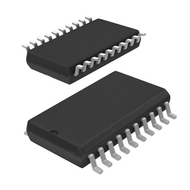
The 74HCT540D,653 is available in a small outline package (SOIC) with 20 pins.
Essence
The essence of this product lies in its ability to amplify and buffer digital signals efficiently and reliably.
Packaging/Quantity
The 74HCT540D,653 is typically packaged in reels or tubes, with a quantity of 2500 units per reel/tube.
Specifications
- Supply Voltage: 2V to 6V
- Input Voltage: 0V to VCC
- Output Voltage: 0V to VCC
- Operating Temperature Range: -40°C to +125°C
- Propagation Delay Time: 10 ns (max)
- Output Current: ±4 mA
Detailed Pin Configuration
- GND (Ground)
- A1 (Input A1)
- Y1 (Output Y1)
- A2 (Input A2)
- Y2 (Output Y2)
- A3 (Input A3)
- Y3 (Output Y3)
- A4 (Input A4)
- Y4 (Output Y4)
- OE (Output Enable)
- GND (Ground)
- Y5 (Output Y5)
- A5 (Input A5)
- Y6 (Output Y6)
- A6 (Input A6)
- Y7 (Output Y7)
- A7 (Input A7)
- Y8 (Output Y8)
- VCC (Supply Voltage)
- GND (Ground)
Functional Features
- Octal buffer/line driver with 3-state outputs
- Non-inverting outputs
- Output enable input for easy control of output states
- High-speed operation allows for efficient signal transmission
- Wide operating voltage range enables compatibility with various systems
- Schmitt-trigger inputs provide noise immunity
Advantages and Disadvantages
Advantages
- High-speed operation ensures fast signal propagation
- Low power consumption leads to energy efficiency
- Compatibility with both TTL and CMOS logic levels allows for versatile use
- Wide operating voltage range enhances flexibility in system design
- Schmitt-trigger inputs provide robustness against noise
Disadvantages
- Limited output current may restrict certain applications requiring higher current drive
- Propagation delay time may affect timing-sensitive circuits
Working Principles
The 74HCT540D,653 is an octal buffer/line driver IC that amplifies and buffers digital signals. It operates by receiving input signals on the A1-A7 pins and providing amplified outputs on the Y1-Y8 pins. The output enable (OE) pin controls the state of the outputs, allowing them to be either active or in a high-impedance state.
Detailed Application Field Plans
The 74HCT540D,653 finds application in various digital electronic systems, including but not limited to: - Microcontrollers - Data communication systems - Memory interfaces - Industrial automation - Automotive electronics
Detailed and Complete Alternative Models
Some alternative models that can be considered as replacements for the 74HCT540D,653 are: - SN74HCT540N - CD74HCT540E - MC74HCT540N - 74HCT540PW,118
These alternatives offer similar functionality and characteristics, providing options for different sourcing preferences.
In conclusion, the 74HCT540D,653 is a versatile integrated circuit that serves as an octal buffer/line driver. Its high-speed operation, low power consumption, and compatibility with various logic levels make it suitable for a wide range of digital electronic applications.
Sebutkan 10 pertanyaan dan jawaban umum terkait penerapan 74HCT540D,653 dalam solusi teknis
Sure! Here are 10 common questions and answers related to the application of 74HCT540D,653 in technical solutions:
Q: What is the function of the 74HCT540D,653? A: The 74HCT540D,653 is an octal buffer/line driver with 3-state outputs. It is used to provide buffering and signal amplification for digital signals.
Q: What is the maximum operating voltage for the 74HCT540D,653? A: The maximum operating voltage for the 74HCT540D,653 is 5.5V.
Q: Can the 74HCT540D,653 be used as a level shifter? A: Yes, the 74HCT540D,653 can be used as a level shifter to convert signals between different voltage levels.
Q: How many input/output pins does the 74HCT540D,653 have? A: The 74HCT540D,653 has 8 input pins and 8 output pins.
Q: What is the maximum output current of the 74HCT540D,653? A: The maximum output current of the 74HCT540D,653 is 35mA.
Q: Can the 74HCT540D,653 be used in high-speed applications? A: Yes, the 74HCT540D,653 is designed for high-speed operation and can be used in applications with fast switching requirements.
Q: Does the 74HCT540D,653 have built-in protection features? A: No, the 74HCT540D,653 does not have built-in protection features. External protection measures may be required to safeguard against voltage spikes or ESD.
Q: Can the 74HCT540D,653 be used in bidirectional communication? A: Yes, the 74HCT540D,653 can be used for bidirectional communication by enabling the 3-state outputs and controlling the direction of data flow.
Q: What is the power supply voltage range for the 74HCT540D,653? A: The power supply voltage range for the 74HCT540D,653 is typically between 4.5V and 5.5V.
Q: Are there any specific layout considerations for using the 74HCT540D,653? A: It is recommended to follow proper PCB layout guidelines, such as minimizing trace lengths, providing decoupling capacitors, and ensuring proper grounding, to optimize performance and minimize noise.
Please note that these answers are general and may vary depending on the specific application and requirements.

