

Lihat spesifikasi untuk detail produk.
MIC4427BMM-TR
Product Overview
Category
The MIC4427BMM-TR belongs to the category of integrated circuits (ICs) specifically designed for driving capacitive, resistive, and inductive loads.
Use
This product is commonly used as a high-speed, low-side MOSFET driver. It provides efficient switching control for various applications such as motor drives, power supplies, and inverters.
Characteristics
- High peak output current capability
- Fast rise and fall times
- Wide operating voltage range
- Low quiescent current
- Thermal shutdown protection
- Undervoltage lockout protection
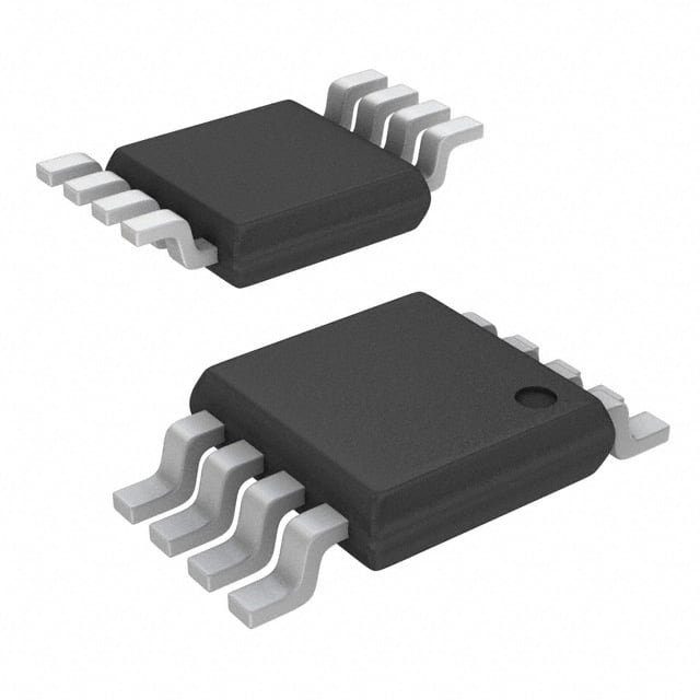
Package
The MIC4427BMM-TR is available in a miniature 8-pin MSOP (Mini Small Outline Package) with exposed pad for enhanced thermal dissipation.
Essence
The essence of the MIC4427BMM-TR lies in its ability to provide reliable and precise control over the switching characteristics of MOSFETs, ensuring optimal performance and efficiency in various load-driving applications.
Packaging/Quantity
This product is typically packaged in tape and reel format, with 3,000 units per reel.
Specifications
- Supply Voltage Range: 4.5V to 18V
- Peak Output Current: 1.8A
- Quiescent Current: 100µA
- Rise/Fall Time: 15ns
- Operating Temperature Range: -40°C to +125°C
Detailed Pin Configuration
The MIC4427BMM-TR features an 8-pin MSOP package with the following pin configuration:
- VDD - Power supply input
- IN - Input control signal
- GND - Ground reference
- LO - Low-side gate driver output
- COM - Common connection for bootstrap capacitor
- HO - High-side gate driver output
- VBS - Bootstrap supply voltage
- VS - High-side floating supply return
Functional Features
- High-speed switching: The MIC4427BMM-TR offers fast rise and fall times, enabling efficient switching of MOSFETs.
- Thermal shutdown protection: The device incorporates a thermal shutdown feature that protects it from excessive temperature, ensuring its longevity.
- Undervoltage lockout protection: The IC includes undervoltage lockout circuitry to prevent improper operation when the supply voltage falls below a specified threshold.
Advantages and Disadvantages
Advantages
- High peak output current capability allows driving of various loads.
- Fast rise and fall times enable efficient switching and reduce power losses.
- Wide operating voltage range provides flexibility in different applications.
- Low quiescent current minimizes power consumption.
- Thermal shutdown and undervoltage lockout protections enhance reliability.
Disadvantages
- Limited to low-side MOSFET driving applications.
- Not suitable for high-power or high-voltage applications.
Working Principles
The MIC4427BMM-TR operates by receiving an input control signal (IN) and generating complementary gate drive signals (LO and HO) for the low-side and high-side MOSFETs, respectively. These gate drive signals control the conduction and blocking states of the MOSFETs, allowing efficient load switching.
Detailed Application Field Plans
The MIC4427BMM-TR finds extensive use in various applications, including:
- Motor Drives: It enables precise control of motor speed and direction in applications such as robotics, industrial automation, and electric vehicles.
- Power Supplies: The IC facilitates efficient switching in power supply circuits, improving overall energy conversion efficiency.
- Inverters: It is employed in inverter circuits for converting DC power to AC power, commonly used in renewable energy systems and motor drives.
Detailed and Complete Alternative Models
- IR2110: A high-voltage, high-speed power MOSFET and IGBT driver with similar features and capabilities.
- TC4427: A low-power, dual MOSFET driver suitable for low-voltage applications.
- MAX4427: An ultra-fast, high-current MOSFET driver designed for demanding load-driving applications.
These alternative models offer similar functionality to the MIC4427BMM-TR and can be considered based on specific application requirements.
Word count: 606 words
Sebutkan 10 pertanyaan dan jawaban umum terkait penerapan MIC4427BMM-TR dalam solusi teknis
Sure! Here are 10 common questions and answers related to the application of MIC4427BMM-TR:
Q: What is MIC4427BMM-TR? A: MIC4427BMM-TR is a high-speed, dual MOSFET driver IC designed for driving N-channel MOSFETs in various applications.
Q: What is the maximum voltage rating of MIC4427BMM-TR? A: The maximum voltage rating of MIC4427BMM-TR is typically around 18V.
Q: Can I use MIC4427BMM-TR to drive other types of transistors besides MOSFETs? A: No, MIC4427BMM-TR is specifically designed for driving N-channel MOSFETs and may not be suitable for other types of transistors.
Q: What is the maximum output current capability of MIC4427BMM-TR? A: MIC4427BMM-TR can typically provide up to 1.5A of peak output current.
Q: Is MIC4427BMM-TR compatible with both 3.3V and 5V logic levels? A: Yes, MIC4427BMM-TR is compatible with both 3.3V and 5V logic levels, making it versatile for different microcontroller or logic interface requirements.
Q: Can I use MIC4427BMM-TR in high-frequency switching applications? A: Yes, MIC4427BMM-TR is designed for high-speed operation and can be used in high-frequency switching applications.
Q: Does MIC4427BMM-TR have built-in protection features? A: Yes, MIC4427BMM-TR has built-in under-voltage lockout (UVLO) and thermal shutdown protection to ensure safe operation.
Q: Can I use MIC4427BMM-TR in automotive applications? A: Yes, MIC4427BMM-TR is suitable for automotive applications as it meets the necessary requirements for automotive-grade components.
Q: What is the typical propagation delay of MIC4427BMM-TR? A: The typical propagation delay of MIC4427BMM-TR is around 25ns, making it suitable for high-speed switching applications.
Q: Can I parallel multiple MIC4427BMM-TR devices to increase output current capability? A: Yes, you can parallel multiple MIC4427BMM-TR devices to increase the overall output current capability if needed. However, proper care should be taken to ensure balanced current sharing between the devices.
Please note that these answers are general and may vary depending on specific datasheet specifications and application requirements.