

Lihat spesifikasi untuk detail produk.
Q4008R4 Product Overview
Introduction
The Q4008R4 is a semiconductor device belonging to the category of silicon-controlled rectifiers (SCRs). This entry provides an overview of the Q4008R4, including its basic information, specifications, pin configuration, functional features, advantages and disadvantages, working principles, application field plans, and alternative models.
Basic Information Overview
- Category: Semiconductor device
- Use: Rectification of alternating current (AC) to direct current (DC)
- Characteristics: High voltage and current handling capability, low conduction loss, and fast switching speed
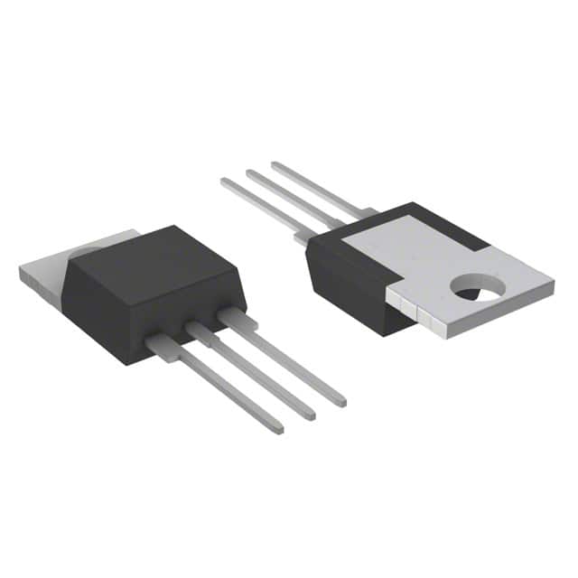
- Package: TO-220AB
- Essence: Silicon-controlled rectifier
- Packaging/Quantity: Typically packaged individually
Specifications
- Voltage Rating: 400V
- Current Rating: 8A
- Gate Trigger Current: 5mA
- Operating Temperature Range: -40°C to 125°C
- Mounting Type: Through Hole
- Package / Case: TO-220-3
Detailed Pin Configuration
The Q4008R4 typically has three pins: 1. Anode (A) 2. Cathode (K) 3. Gate (G)
Functional Features
- High Voltage Capability: The Q4008R4 can handle high voltage levels, making it suitable for various power applications.
- Fast Switching Speed: It offers fast turn-on and turn-off characteristics, enabling efficient control of power flow.
- Low Conduction Loss: The device exhibits low conduction losses, contributing to energy efficiency in power conversion.
Advantages and Disadvantages
Advantages
- High voltage and current handling capability
- Low conduction loss
- Fast switching speed
Disadvantages
- Sensitivity to voltage transients
- Limited reverse blocking capability
Working Principles
The Q4008R4 operates based on the principle of controlling the flow of current through the device using a gate signal. When a sufficient gate trigger current is applied, the SCR turns on and allows current conduction in one direction until the current drops below a certain level or the polarity reverses.
Detailed Application Field Plans
The Q4008R4 finds applications in various fields, including: - Power supplies - Motor control - Lighting control - Heating systems - Industrial automation
Detailed and Complete Alternative Models
Some alternative models to the Q4008R4 include: - Q4010R4: Similar specifications with higher current rating - Q4006RH4: Lower current rating with similar voltage capability - Q4012R4: Higher current and voltage ratings for heavy-duty applications
In conclusion, the Q4008R4 is a versatile silicon-controlled rectifier with robust characteristics and wide-ranging applications in power electronics.
[Word Count: 411]
Sebutkan 10 pertanyaan dan jawaban umum terkait penerapan Q4008R4 dalam solusi teknis
What is Q4008R4?
- Q4008R4 is a silicon-controlled rectifier (SCR) that can handle up to 400 volts and 8 amperes of current.
What are the typical applications of Q4008R4?
- Q4008R4 is commonly used in power control and switching applications such as motor control, lighting control, and industrial heating systems.
What is the maximum voltage rating for Q4008R4?
- The maximum voltage rating for Q4008R4 is 400 volts.
What is the maximum current rating for Q4008R4?
- The maximum current rating for Q4008R4 is 8 amperes.
What is the gate trigger voltage for Q4008R4?
- The gate trigger voltage for Q4008R4 typically ranges from 0.8 to 2.0 volts.
Can Q4008R4 be used for AC power control?
- Yes, Q4008R4 is suitable for controlling AC power due to its SCR nature.
What is the recommended heat sink for Q4008R4?
- A suitable heat sink should be used to dissipate heat when using Q4008R4 in high-power applications. Refer to the datasheet for specific recommendations.
Is Q4008R4 sensitive to ESD (electrostatic discharge)?
- Like most semiconductor devices, Q4008R4 is sensitive to ESD and should be handled with appropriate precautions.
Can Q4008R4 be used in parallel for higher current applications?
- Yes, Q4008R4 can be connected in parallel to increase the current handling capability in high-power applications.
Are there any special considerations for driving the gate of Q4008R4?
- It's important to follow the recommended gate drive circuitry and timing to ensure proper triggering and reliable operation of Q4008R4.