

Lihat spesifikasi untuk detail produk.
IRF6714MTR1PBF
Product Overview
Category: Power MOSFET
Use: Switching applications in power supplies and motor control
Characteristics: High efficiency, low on-resistance, fast switching speed
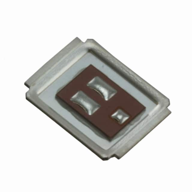
Package: D2PAK
Essence: Power MOSFET for high-performance switching applications
Packaging/Quantity: Tape & Reel, 800 units per reel
Specifications
- Voltage - Drain-Source Breakdown (Vds): 20V
- Current - Continuous Drain (Id) @ 25°C: 100A
- Rds On (Max) @ Id, Vgs: 3.5 mOhm @ 50A, 10V
- Vgs(th) (Max) @ Id: 2.35V @ 250µA
- Gate Charge (Qg) @ Vgs: 60nC @ 10V
- Input Capacitance (Ciss) @ Vds: 6000pF @ 15V
- Power Dissipation (Max): 2.5W
Detailed Pin Configuration
- Gate (G)
- Drain (D)
- Source (S)
Functional Features
- Low on-resistance for high efficiency
- Fast switching speed for improved performance
- Suitable for high-frequency switching applications
Advantages
- High efficiency
- Low on-resistance
- Fast switching speed
Disadvantages
- Limited voltage and current ratings compared to some other MOSFETs
- Sensitive to static electricity
Working Principles
The IRF6714MTR1PBF operates based on the principles of field-effect transistors, utilizing the voltage applied to the gate terminal to control the flow of current between the drain and source terminals.
Detailed Application Field Plans
This MOSFET is commonly used in power supplies, motor control circuits, and other switching applications where high efficiency and fast switching speeds are essential. It is suitable for use in DC-DC converters, synchronous rectification, and motor drive circuits.
Detailed and Complete Alternative Models
- IRF6721MTRPBF: Similar characteristics with higher voltage and current ratings
- IRF6628MTRPBF: Lower on-resistance with comparable voltage and current ratings
- IRF6637MTRPBF: Higher input capacitance but lower gate charge
Note: The alternative models listed above are for reference purposes and may require additional evaluation based on specific application requirements.
This content provides a comprehensive overview of the IRF6714MTR1PBF, including its specifications, pin configuration, functional features, advantages, disadvantages, working principles, application field plans, and alternative models. If you need further details or modifications, feel free to let me know!
Sebutkan 10 pertanyaan dan jawaban umum terkait penerapan IRF6714MTR1PBF dalam solusi teknis
What is the maximum drain-source voltage of IRF6714MTR1PBF?
- The maximum drain-source voltage of IRF6714MTR1PBF is 30V.
What is the continuous drain current of IRF6714MTR1PBF?
- The continuous drain current of IRF6714MTR1PBF is 17A.
What is the on-state resistance of IRF6714MTR1PBF?
- The on-state resistance of IRF6714MTR1PBF is typically 6.5mΩ.
What is the gate threshold voltage of IRF6714MTR1PBF?
- The gate threshold voltage of IRF6714MTR1PBF is typically 1V.
What are the typical applications for IRF6714MTR1PBF?
- IRF6714MTR1PBF is commonly used in power management, motor control, and DC-DC converter applications.
What is the operating temperature range of IRF6714MTR1PBF?
- The operating temperature range of IRF6714MTR1PBF is -55°C to 150°C.
Is IRF6714MTR1PBF suitable for automotive applications?
- Yes, IRF6714MTR1PBF is suitable for automotive applications due to its high current capability and robustness.
Does IRF6714MTR1PBF require a heat sink for high-power applications?
- Yes, for high-power applications, it is recommended to use a heat sink to ensure proper thermal management.
What is the package type of IRF6714MTR1PBF?
- IRF6714MTR1PBF comes in a D2PAK package.
Is IRF6714MTR1PBF RoHS compliant?
- Yes, IRF6714MTR1PBF is RoHS compliant, making it suitable for environmentally friendly designs.