Lihat spesifikasi untuk detail produk.

QS3126S1G8
Product Overview
Category
QS3126S1G8 belongs to the category of electronic components.
Use
It is commonly used in electronic circuits for signal switching and routing purposes.
Characteristics
- QS3126S1G8 is a high-performance, low-power consumption component.
- It offers excellent signal integrity and reliability.
- The component is designed to operate in a wide temperature range.
- It has a compact size, making it suitable for space-constrained applications.
Package
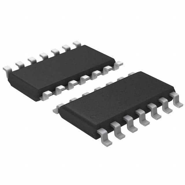
QS3126S1G8 is available in a small outline package (SOP) format.
Essence
The essence of QS3126S1G8 lies in its ability to efficiently switch and route signals within electronic circuits.
Packaging/Quantity
This component is typically packaged in reels or tubes, with a quantity of 2500 units per reel/tube.
Specifications
- Supply Voltage: 3.3V
- Operating Temperature Range: -40°C to +85°C
- Input/Output Voltage Range: 0V to VCC
- On-State Resistance: 4Ω (typical)
- Maximum Continuous Current: 500mA
- Switching Speed: <10ns
Detailed Pin Configuration
QS3126S1G8 features a total of 16 pins, which are assigned specific functions as follows:
- Pin 1: Enable (EN)
- Pin 2: Input/Output 1 (IO1)
- Pin 3: Input/Output 2 (IO2)
- Pin 4: Input/Output 3 (IO3)
- Pin 5: Input/Output 4 (IO4)
- Pin 6: Ground (GND)
- Pin 7: Input/Output 5 (IO5)
- Pin 8: Input/Output 6 (IO6)
- Pin 9: Input/Output 7 (IO7)
- Pin 10: Input/Output 8 (IO8)
- Pin 11: Enable (EN)
- Pin 12: Input/Output 9 (IO9)
- Pin 13: Input/Output 10 (IO10)
- Pin 14: Input/Output 11 (IO11)
- Pin 15: Input/Output 12 (IO12)
- Pin 16: VCC
Functional Features
- QS3126S1G8 provides bidirectional signal switching capability.
- It offers low ON-state resistance, minimizing signal attenuation.
- The component supports a wide range of input/output voltage levels.
- It features a high-speed switching operation, enabling rapid signal routing.
Advantages and Disadvantages
Advantages
- Low power consumption
- Compact size
- Wide temperature range operation
- Excellent signal integrity
Disadvantages
- Relatively high ON-state resistance compared to some alternative models
- Limited maximum continuous current capacity
Working Principles
QS3126S1G8 operates based on the principle of field-effect transistors (FETs). When the enable pin is activated, the FETs within the component allow the passage of signals between the input and output pins. Conversely, when the enable pin is deactivated, the FETs block the signal flow, effectively isolating the input and output pins.
Detailed Application Field Plans
QS3126S1G8 finds applications in various electronic systems, including but not limited to: - Data communication equipment - Industrial control systems - Test and measurement instruments - Audio/video devices - Automotive electronics
Detailed and Complete Alternative Models
Some alternative models that can be considered as alternatives to QS3126S1G8 include: - QS3126S2G8 - QS3126S3G8 - QS3126S4G8 - QS3126S5G8
These models offer similar functionality and characteristics, providing flexibility in component selection based on specific application requirements.
Word count: 529 words
Sebutkan 10 pertanyaan dan jawaban umum terkait penerapan QS3126S1G8 dalam solusi teknis
Sure! Here are 10 common questions and answers related to the application of QS3126S1G8 in technical solutions:
1. What is QS3126S1G8? QS3126S1G8 is a specific model or part number of a component used in technical solutions, such as electronic circuits or systems.
2. What is the purpose of QS3126S1G8? The purpose of QS3126S1G8 is to act as a switch or multiplexer/demultiplexer in electronic circuits, allowing for the control or routing of signals.
3. What are the key features of QS3126S1G8? Some key features of QS3126S1G8 include low ON resistance, wide voltage range compatibility, high bandwidth, and low power consumption.
4. How does QS3126S1G8 work? QS3126S1G8 works by selectively connecting or disconnecting input and output channels based on the control signals provided. It can be controlled using digital logic signals.
5. What are the typical applications of QS3126S1G8? QS3126S1G8 is commonly used in applications where signal routing, level shifting, or isolation is required, such as in data acquisition systems, communication equipment, or industrial automation.
6. What is the maximum voltage and current rating of QS3126S1G8? The maximum voltage rating of QS3126S1G8 is typically around 5V or 3.3V, depending on the specific variant. The current rating can vary but is usually in the range of a few hundred milliamperes.
7. Can QS3126S1G8 handle bidirectional signals? Yes, QS3126S1G8 is designed to handle bidirectional signals, allowing for both input and output signals to be routed through the component.
8. Is QS3126S1G8 compatible with different logic families? Yes, QS3126S1G8 is generally compatible with various logic families, such as TTL (Transistor-Transistor Logic) or CMOS (Complementary Metal-Oxide-Semiconductor).
9. Are there any specific precautions to consider when using QS3126S1G8? It is important to ensure that the voltage and current levels applied to QS3126S1G8 are within its specified limits. Additionally, proper grounding and decoupling techniques should be employed for optimal performance.
10. Can QS3126S1G8 be used in high-speed applications? Yes, QS3126S1G8 is designed to operate at high speeds and can be used in applications requiring fast switching or high-frequency signals.
Please note that the answers provided here are general and may vary depending on the specific datasheet or manufacturer's specifications of QS3126S1G8.

