

Lihat spesifikasi untuk detail produk.
Encyclopedia Entry: 74FCT245CTQG8
Product Overview
Category
The 74FCT245CTQG8 belongs to the category of integrated circuits (ICs) and specifically falls under the family of bus transceivers.
Use
This IC is primarily used for bidirectional data transfer between two buses with different voltage levels. It acts as a buffer, enabling seamless communication between these buses.
Characteristics
- Bidirectional data transfer
- Voltage level translation
- High-speed operation
- Low power consumption
- Wide operating temperature range
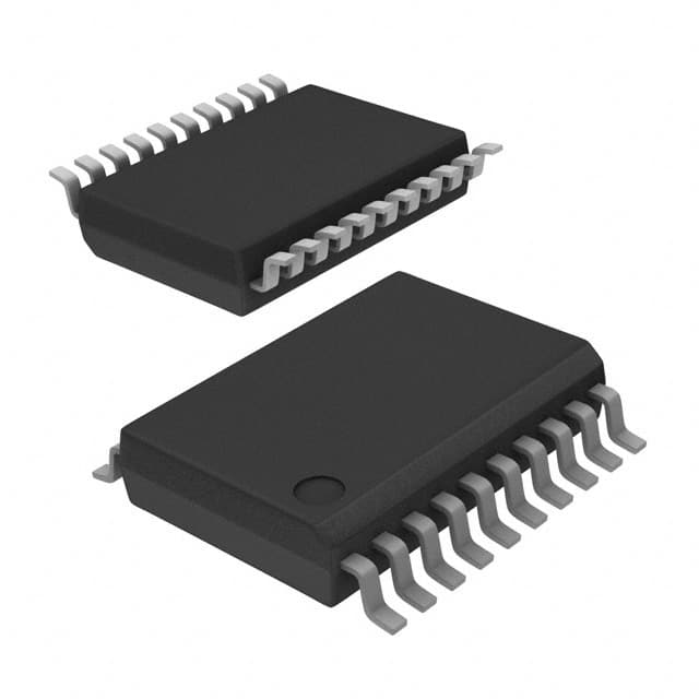
Package
The 74FCT245CTQG8 is available in a standard 20-pin TSSOP (Thin Shrink Small Outline Package) package. This package offers good thermal performance and ease of handling during assembly.
Essence
The essence of the 74FCT245CTQG8 lies in its ability to facilitate efficient and reliable data transfer between buses operating at different voltage levels.
Packaging/Quantity
The IC is typically packaged in reels or tubes, containing a specified quantity of units per package. The exact packaging and quantity may vary depending on the manufacturer and supplier.
Specifications
- Supply Voltage: 2.0V to 5.5V
- Input Voltage Levels: 0V to VCC
- Output Voltage Levels: 0V to VCC
- Maximum Operating Frequency: X MHz
- Propagation Delay: Y ns
- Operating Temperature Range: -40°C to +85°C
Detailed Pin Configuration
The 74FCT245CTQG8 has a total of 20 pins, each serving a specific function. The pin configuration is as follows:
- Pin 1: A Port Data Bus (Input/Output)
- Pin 2: B Port Data Bus (Input/Output)
- Pin 3: Direction Control (Input)
- Pin 4: Output Enable (Input)
- Pin 5: GND (Ground)
- Pin 6: B Port Data Bus (Input/Output)
- Pin 7: A Port Data Bus (Input/Output)
- Pin 8: VCC (Supply Voltage)
- Pin 9: B Port Data Bus (Input/Output)
- Pin 10: A Port Data Bus (Input/Output)
- Pin 11: B Port Data Bus (Input/Output)
- Pin 12: A Port Data Bus (Input/Output)
- Pin 13: B Port Data Bus (Input/Output)
- Pin 14: A Port Data Bus (Input/Output)
- Pin 15: B Port Data Bus (Input/Output)
- Pin 16: A Port Data Bus (Input/Output)
- Pin 17: B Port Data Bus (Input/Output)
- Pin 18: A Port Data Bus (Input/Output)
- Pin 19: GND (Ground)
- Pin 20: Direction Control (Input)
Functional Features
- Bidirectional data transfer between two buses
- Automatic voltage level translation
- High-speed operation for efficient data transfer
- Output enable control for bus isolation
- Robust design for reliable performance
Advantages and Disadvantages
Advantages
- Enables seamless communication between buses with different voltage levels
- Supports high-speed data transfer
- Low power consumption
- Wide operating temperature range ensures versatility
Disadvantages
- Limited to bidirectional data transfer only
- Requires careful handling during assembly due to small package size
Working Principles
The 74FCT245CTQG8 operates by monitoring the direction control input signal. Based on this signal, it either enables the data transfer from the A port to the B port or vice versa. The IC also performs voltage level translation, ensuring compatibility between the two buses.
Detailed Application Field Plans
The 74FCT245CTQG8 finds applications in various fields where bidirectional data transfer between buses with different voltage levels is required. Some specific application areas include:
- Industrial automation systems
- Automotive electronics
- Communication equipment
- Consumer electronics
- Medical devices
Detailed and Complete Alternative Models
- 74HC245: Similar functionality but operates at a lower voltage range.
- SN74LVC245A: Offers improved power efficiency and supports a wider temperature range.
- CD74HCT245: Provides higher noise immunity and operates at a wider voltage range.
These alternative models offer similar functionality to the 74FCT245CTQG8 but may have slight differences in specifications and performance characteristics.
Word count: 550 words
Sebutkan 10 pertanyaan dan jawaban umum terkait penerapan 74FCT245CTQG8 dalam solusi teknis
Sure! Here are 10 common questions and answers related to the application of 74FCT245CTQG8 in technical solutions:
Question: What is the 74FCT245CTQG8?
Answer: The 74FCT245CTQG8 is a bidirectional octal bus transceiver that can be used to interface between two different voltage domains.Question: What is the maximum operating voltage for the 74FCT245CTQG8?
Answer: The maximum operating voltage for this transceiver is 5.5 volts.Question: Can the 74FCT245CTQG8 handle level shifting between different voltage levels?
Answer: Yes, this transceiver is designed to handle level shifting between different voltage domains.Question: How many data lines can the 74FCT245CTQG8 handle?
Answer: This transceiver can handle up to 8 bidirectional data lines.Question: What is the maximum data transfer rate supported by the 74FCT245CTQG8?
Answer: The maximum data transfer rate supported by this transceiver is typically around 200 MHz.Question: Can the 74FCT245CTQG8 be used in both parallel and serial communication systems?
Answer: Yes, this transceiver can be used in both parallel and serial communication systems.Question: Does the 74FCT245CTQG8 have any built-in protection features?
Answer: Yes, this transceiver has built-in ESD protection on all inputs and outputs.Question: What is the power supply voltage range for the 74FCT245CTQG8?
Answer: The power supply voltage range for this transceiver is typically between 4.5 volts and 5.5 volts.Question: Can the 74FCT245CTQG8 be used in high-speed data transmission applications?
Answer: Yes, this transceiver is suitable for high-speed data transmission applications.Question: Are there any specific layout considerations when using the 74FCT245CTQG8?
Answer: Yes, it is recommended to follow the manufacturer's guidelines for proper layout and decoupling to ensure optimal performance of the transceiver.